Classifications Scenarios
vIn
contention-based random access, the access may fail because a random
access channel (RACH) may not be allocated to the UE.
vIn
non-contention-based random access, the eNodeB allocates a dedicated RACH
to the UE to ensure successful access. If dedicated RACHs are insufficient, the
eNodeB instructs the UE to initiate contention-based random access.
RACH Optimization
RACH Resource Adjustment
RACH resources include a physical random access channel (PRACH) configuration index and preamble groups
ØPRACH Configuration Index:
§The PRACH configuration index indicates the number of PRACHs in each radio frame and the subframe number of each PRACH.
ØPreamble Groups:
§Random access preambles in a cell are grouped into random preambles and dedicated preambles, which are used for contention-based random access and non-contention-based random access, respectively.
RACH Power Control Adjustments
—PRACH power control parameter adjustment is performed based on the random access information reported by the UE, (which will be explained in details in Power Control Session)
PRACH False Alarm Detection
—If a UE does not send a preamble but the eNodeB detects a preamble from the UE during a random access procedure, this falsely detected preamble is called a PRACH false alarm. For a falsely detected preamble, the eNodeB does not send a Random Access Response message or increment related counters.
Random access scenarios
qScenario
1: Initial RRC connection setup
To switch
from the RRC_IDLE state to the RRC_CONNECTED state, a UE initiates random
access.
qScenario
2: RRC connection reestablishment
When a
radio link failure (RLF) occurs, the UE needs to reestablish an RRC connection.
In this scenario, the UE initiates random access.
qScenario
3: Handover
During
a
handover, a UE initiates random access in the target cell.
qScenario
4: Downlink data arrival
When an
eNodeB needs to send downlink data to a UE in the RRC_CONNECTED state and finds
that the UE is out of uplink synchronization, the eNodeB instructs the UE to
initiate random access.
qScenario
5: Uplink data arrival
When a UE
in the RRC_CONNECTED state needs to send uplink data to an eNodeB and finds
that it is out of uplink synchronization, the UE initiates random access.
Random Access
Preambles
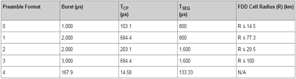
—During random access, the eNodeB allocates a random access preamble to a UE. The UE sends the random access preamble to the eNodeB to initiate a random access request. The random access preamble is a burst, which consists of a cyclic prefix (CP), a preamble sequence, and an extra part in the time domain and six resource blocks in the frequency domain. TCP denotes the length of a CP, and TSEQ denotes the length of a preamble sequence.
Preamble Frame Format
—The Guard Period is required since the eNB does not know when the preambles will arrive.
—The below figures illustrate an example with two UEs. The first is next to the eNB therefore there is very little delay. In contrast UE “B” is some distance from the eNB, as such the initial access preamble is delayed, i.e. there is a round trip delay. The eNB must allocate a large enough window such that the preambles from UE at the edge of the cell don’t arrive outside of this window.
Preamble Sequence Grouping
CONTENTION BASED
Contention Based Random Access Procedure
—The following slides describe the four steps shown below, which involves random access preamble transmission, random access response, scheduled uplink transmission, and contention resolution transmission.
1- Random Access Preamble Transmission
ØIn contention-based random access, the UE directly sends a random access preamble to the eNodeB if the PRACH configuration has been specified and has not expired. If the PRACH configuration has not been specified or has expired, the UE must obtain the PRACH configuration first.
ØThe UE selects random group B if the following conditions are met:
1.Random group B exists.
2.The size of Msg3 (the third message transmitted in the random access procedure shown above) is larger than the corresponding threshold configured for random group A.
3.The path loss of the UE is less than the threshold.
vNote: If any of the preceding conditions are not met, the UE selects random group A.
ØAfter a random group is determined, the UE selects a preamble from the group randomly.
ØThe UE sends a random access preamble on the newly arriving PRACH with the power PPRACH. The preamble usually consists of six bits, where five bits indicate an RA-RNTI of a UE and one bit indicates the size of Msg3. RA-RNTI stands for random access - radio network temporary identifier.
2-Random Access Response
—Upon receiving the preamble, the eNodeB applies for a temporary cell RNTI (C-RNTI) and uplink and downlink resources for scheduling. Then, the eNodeB sends a random access response over the downlink shared channel (DL-SCH) for each UE.
—The response contains the RA-preamble identifier, timing alignment information, initial uplink grant, and temporary C-RNTI. One DL-SCH can carry random access responses to multiple UEs.
—After the UE sends the preamble, it monitors the physical dedicated control channel (PDCCH) and waits for a random access response within a random access response window:
ØIf the UE receives a response that contains an RA-preamble identifier matching the transmitted random access preamble, the response is successful.
ØIf the UE does not receive a response or fails to verify the response reception, the response fails.
qIn this case, if the number of random access attempts is smaller than the maximum, the UE attempts random access again. Otherwise, random access fails. The maximum number of random access attempts of the UE can be obtained from SIB2.
3- Scheduled Uplink Transmission
—After receiving a successful response, the UE sends scheduled uplink transport block over the uplink shared channel (UL-SCH).
—The information in the transport block sent by the UE varies according to the following random access scenarios:
ØIn initial RRC connection setup;
The RRC Connection Request message (including NAS UE_ID) is transmitted over the CCCH in TM at the RLC layer. The message is not segmented.
ØIn RRC connection reestablishment;
The RRC Connection Reestablishment Request message (excluding NAS information) is transmitted in TM at the RLC layer. The message is not segmented.
ØIn contention-based random access due to no dedicated preamble after a handover;
The RRC Handover Confirm message and C-RNTI are transmitted over the DCCH. If required, a buffer status report (BSR) is also carried.
ØIn other scenarios;
At least the C-RNTI of the UE is transmitted.
4- Contention Resolution Transmission
—After the UE sends Msg3 (Scheduled transmission), a contention resolution timer starts. The contention resolution timer can be obtained from SIB2.
—Within the timer period, the eNodeB performs contention resolution at the MAC layer and informs the UE of the resolution by the C-RNTI on the PDCCH or by the information element (IE) UE Contention Resolution Identity on the DL-SCH.
—The UE monitors the PDCCH before the timer expires. The UE considers the contention resolution as successful, notifies upper layers, and stops the timer if one of the following conditions is met:
ØThe UE obtains the C-RNTI from the PDCCH.
ØThe UE obtains the temporary C-RNTI over the PDCCH, the MAC packet data unit (PDU) is successfully decoded, and the MAC PDU contains information matching the CCCH service data unit (SDU) transmitted in Msg3.
—If the contention resolution is successful, the contention-based random access procedure ends. If the contention resolution timer expires, the UE considers the contention resolution as failed. Then, the UE performs random access again if the number of random access attempts is smaller than the maximum. If the number of random access attempts is not smaller than the maximum, the random access procedure fails.
NON-CONTENTION BASED
—Unlike
contention-based random access, non-contention-based random access does not
involve contention and conflict resolution because random access preambles are
allocated by the eNodeB. Other procedures in non-contention-based random access
are similar to those in contention-based random access. Below
figure shows the
non-contention-based random access procedure.
Please find the below link as a reference for attach procedure
http://www.eventhelix.com/lte/attach/LTE-RRC-Connection-Setup-Messaging.pdf
Attach Procedure
RACH: UE à eNodeB: Random Access
Preamble
—•The terminal picks a preamble to send the random access message
— •The preambles in LTE are defined from a Zadoff-Chu sequence
— •The preamble consists of the cyclic prefix and a sequence
— •The sequence identifies the UE that is initiating the random access
—• The type of the UE and the UE ID value are included in the message
— RA-RNTI is used as a temporary identifier during the random access procedure
DL-SCH: UEß eNodeB: Random Access Response
•—The eNodeB responds with a Random Access Response on the DL-SCH channel
—•The UE is addressed with the RARNTI that was sent in the Random Access Preamble
— •The message carries a Timing Advance that is used to adjust the UE transmitter timing
•—This adjustment will synchronize the UE transmitter so that the transmissions from the UE are received within the receive timing window
•—The message may carry an uplink resource assignment
—•The message also assigns a C-RNTI that will be used to address the UE.
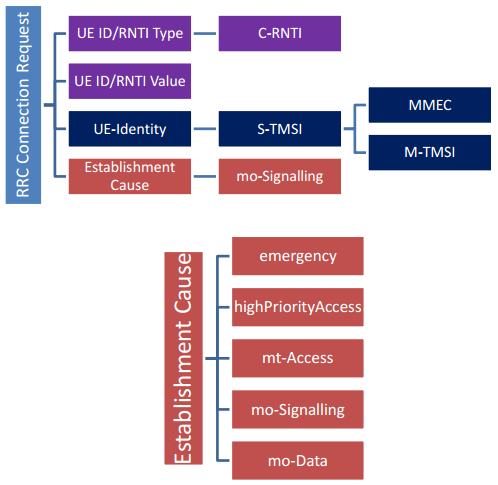
UL-SCH: UE à eNodeB RRC Connection Request
—•The UE has received the Random Access Response based on the RA-RNTI.
Ø The Random Access Response assigns a C-RNTI and resources for transmission of the RRC Connection Request
•The message identifies the UE with the C-RNTI
•The message contains the UE-Identity
Ø IMSI is sent in the message if this is the first attach to the network.
Ø If the terminal had attached previously, the S-TMSI is included in the message.
•—The message also contains the establishment cause. •
ØIn this example, the RRC Connection Request is sent with “Mobile Originated Signaling” cause.
vNote that the eNodeB may optionally send a contention resolution message on receipt of this message.
DL-SCH: UE ß eNodeB RRC Connection
Setup
—•The message identifies the signaling radio bearer (SRB).
—•The configuration parameters carried in the message are described in the next points.
UL-SCH: UE à eNodeB RRC Connection
Setup Complete
—UE
sends this message on receipt of the RRC Connection Setup message.
— “Dedicated
Info NAS” is used to transfer UE specific NAS layer information between the
network and the UE. The RRC layer is transparent for this information.
— The
message may optionally contain registered MME.
—The RRC
Connection Setup Complete may also carry octets for a NAS message exchanged
between the UE and the MME.