Friday, December 4, 2015

System Frame Number (SFN) and Subframe Number

SFN and Subframe

In any communication, one of the most important requirement would be that the transmitter and receiver operate at the same tempo, more technically speaking that the transmitter and receiver should operates in synchronized mode.

Speaking in laymen's terminology, the transmitter and receiver has it's own clock and they have to synchronize the clock before the communication starts.

What kind of clock they have in LTE ? Like our analog wrist clock, LTE clock has two arms. One arm ticks every 10 ms and the other arm ticks every 1 ms. Again as in the wrist clock, each of ticks has specific numbers and the numbers has a certain range.

In LTE, the arm ticking in 10 ms interval has numbers between 0 and 1023 and these numbers are called SFN (System Frame Number) and the other arm ticking in 1 ms interval has numbers between 0 and 9, and this number is called subframe number.

Before the transmitter (eNode B) and the receiver (UE) in LTE start communicating each of other they have to set these two clock arms to be the same number and this synchronization happens during cell search and timing sync process. In short, they synchronize the tempo (exact time the arm ticks) by cell search and timing sync and UE get SFN sync from MIB which carries SFN number in it.

Friday, October 16, 2015

What is radio retransmission in LTE?

  • The radio retransmission mechanism is called Hybrid Automatic Request (H-ARQ).
  • H-ARQ allows to retransmit fastly erroneous blocks between the eNodeB and the UE.
  • It avoids long retransmission between 2 TCP layers.
The H-ARQ process runs in the eNodeB and in the UE.
The H-ARQ is based on ACK/NACK messages carried by PUCCH or PUSCH.
The LA1.X implementation is a hard HARQ technique:
  • It reserves the same RB resources & MCS used for the initial transmission.
  • Using information that was sent in the previous transmissions of the same block to increase the probability of decoding.
  • If data block not received correctly, soft values are stored in order to reuse them after the retransmission of the block.
  • When data is retransmitted, a different puncturing scheme is used so that the transmitted bit do not carry the same information as the first time.
  • If puncturing schemes are disjoint between two transmission, number of coded bits transmitted after the second transmission is twice as high, thus coding rate has been divided by 2. After the third transmission, coding rate has been divided by 3. Probability to decode the block is increased after each transmission.

Saturday, October 10, 2015

Detach Cases in LTE

 1) Detach Case 1: UE-initiated Detach

UE can initiate detach: 

  • if UE is turned off
  • if a USIM card is removed from UE
  • if UE is attempting to use a non-EPS service (e.g. CS fallback, SMS, etc.)

2) Detach Case 2: MME-initiated Detach

MME-initiated detach can be further divided into explicit detach and implicit detach. In case of explicit detach, MME notifies UE of its intent to detach in advance by sending a Detach Request message, and informs the UE whether it has to attach the network again or not after detach. In case of implicit detach, however, the MME initiates detach procedures without notification (i.e. without sending a Detach Request message) because the UE is not capable of communicating with the MME. MME can initiate:


i) Explicit Detach

  • for an operator’s O&M (Operation & Maintenance) purposes
  • if re-authentication fails
  • if it cannot provide the resources allocated to a user

ii) Implicit Detach

  • if it is not able to communicate with a user because of poor radio link quality (e.g. radio link failure)

3) Detach Case 3: HSS-initiated Detach

HSS can initiate detach:

  • if the user profile provisioned in HSS is changed, and thus the one saved in MME also has to be changed
  • if an operator is trying to restrict access by an illegal UE (e.g. a stolen device) to its network

The next three chapters (III, IV and V) describe different detach procedures required in the three detach cases mentioned above. In all three cases, it is assumed a user is in EMM-Registered, ECM-Connected and RRC-Connected state before detach, and services are provided through the default EPS bearer only. Figure 1 illustrates what connections are established, and in what state UE and MME are in user/control planes before and after detach. Before detach, a default EPS bearer and its related control connections are established, and the user is in EMM-Registered, ECM-Connected and RRC-Connected. Then, after detach, the default EPS bearer and all the signaling connections are released, and the user enters EMM-Deregistered, ECM-Idle and RRC-Idle state.  


Figure 1. Connections and States before/after Detach


III. UE-initiated Detach


Figure 2 shows how user-initiated detach is performed. The detach procedure for this type of detach begins when detach triggering is detected at UE (see Chapter II), and thus the UE sends a Detach Request message. The procedure ends when the UE receives a Detach Accept message from MME, unless the UE is turned off by the user.


Figure 2. Procedure for UE-initiated Detach


 Detach Triggering by UE

When detach triggering is detected at UE, and thus the UE and MME become aware of it, the two entities will begin the following procedures:


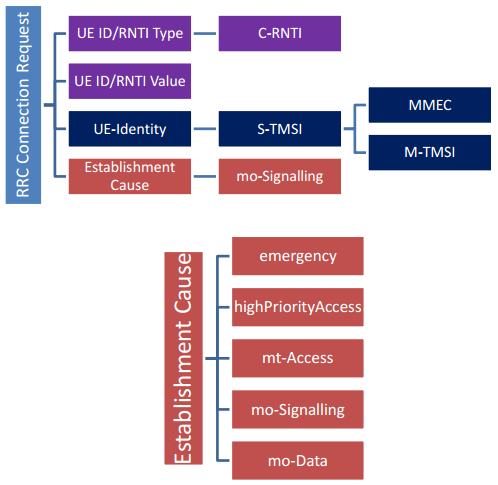
1) [UE → MME] Detach Request

The UE requests the MME for detach by sending a Detach Request message to the MME. Interpretation of the Detach Request message parameters varies depending on which direction the message is delivered. If it is from UE to MME, the message parameters will be as follows:


2) [UE] Handling Security and Bearer Contexts

After sending the Detach Request message, the UE stores its current NAS security context, GUTI and TA information, and then deletes its EPS bearer context.


3) [MME] Noticing Detach Intent and Handling Security Context

After receiving the Detach Request message from the UE, the MME becomes aware of the UE’s intent to detach. It then stores the user’s current NAS security context, and checks the type of the intended detach, i.e. whether it is a case of normal detach, or a turned off device. By doing this, the MME finds out whether it has to send a Detach Accept message or not.


❷ EPS Session Termination

Once the MME perceived UE-initiated detach and stored the user’s current NAS security context, it requests for termination of the activated EPS session. This request triggers PCEF (P-GW)-initiated EPS termination, releasing all the network/radio resources allocated to the user, as to be described below.


(1) EPS Bearer Release and PCC Rule Removal


4) [MME → S-GW] Requesting EPS Session Release

The MME and the S-GW communicate with each other over S11 interface using GTP protocol (GTP-C). The MME begins procedures for deleting the user’s EPS session and default EPS bearer by sending the S-GW a Delete Session Request message. At this time, the default EPS bearer ID and UE location information (ECGI, TAI) are delivered.


5) [MME] Deleting EPS Bearer Context

The MME deletes the user’s EPS bearer context after sending the Delete Session Request message.


6) [S-GW → P-GW] Requesting EPS Session Release

The S-GW and the P-GW communicate with each other over S5 interface using GTP protocol (UP: GTP-U, CP: GTP-C). The S-GW forwards the Delete Session Request message received from the MME to the P-GW.


7) [S-GW] Deleting EPS Bearer Context

The S-GW deletes the user’s EPS bearer context after sending the Delete Session Request message.


8) [P-GW → PCRF] Notifying of EPS Session Termination

The P-GW and the PCRF communicate with each other over Gx interface using Diameter protocol. The P-GW sends PCRF a CCR (CC-Request) message to notify the user has finished using services through the network. This way it has the EPS session termination procedures (PCEF-initiated EPS Session Termination) initiated.


9) [PCRF] Deleting RCC Rule

The PCRF deletes the user’s PCC rule once it receives the CCR message from the P-GW.


10) [P-GW ← PCRF] Acknowledging EPS Session Termination

The PCRF acknowledges the user’s PCC rule has been deleted by sending a CCA (CC-Answer) message to the P-GW.


11) [S-GW ← P-GW] Responding to EPS Session Release Request

When the P-GW receives the CCA message from the PCRF, it sends the S-GW a Delete Session Response message as a response to the message sent in Step 6) above.


12) [P-GW] Deleting EPS Bearer Context

The P-GW deletes the user’s EPS bearer context after sending the Delete Session Response message.


13) [MME ← S-GW] Responding to EPS Session Release Request

When the S-GW receives the Delete Session Response message from the P-GW, it sends the MME a Delete Session Response message as a response to the message sent in Step 4) above.


14) [UE ← MME] Acknowledging Detach

Upon receipt of the Delete Session Response message, the MME recognizes the user’s resource release has been approved by the PCRF. So, it sends the UE a Detach Accept message as a response to the request sent in Step 1). A Detach Accept message is sent only when the UE’s detach request was made due to a cause other than a switched off device (i.e. when Switch Off=0 in the Detach Request). If detach was requested because of a device’s switch off, no Detach Accept message is sent by MME.   


(2) S1 Signaling Connection Release

After sending the Detach Accept message to the UE, the MME and the eNB release any resources left for the user (S1 signaling connection, RRC connection and UE Context left in the eNB) as they do not serve the UE any more.


15) [eNB ← MME] Acknowledging S1 Signaling Connection Release

The MME sends a UE Context Release Command message to the eNB to release the S1 signaling connection.


16) [UE ← eNB] RRC Connection Release

The eNB sends an RRC Connection Release message to the UE to release any RRC connection left unleased.


17) [eNB] Deleting UE Context

The eNB deletes all the information related to the UE.


18) [eNB → MME] RRC Connection Release Complete

Finally, the eNB sends the MME a UE Context Release Complete message as a response to the request sent in Step 15).


IV. MME-initiated Detach


Figure 3 displays how MME-initiated explicit detach is performed. The detach procedure for this type of detach begins when detach triggering is detected at MME, and thus the MME sends a Detach Request message to the UE. The procedure ends when the resources previously allocated to the UE’s EPS session are released.


Figure 3. Procedure for MME-initiated Detach


 Detach Triggering by MME

Below is a description of the procedures to be performed after MME detects detach triggering, and before the EPS session termination procedure is carried out. If the user is in Idle state at this time, the MME performs paging to establish S1 signaling connection (Detailed paging procedures will be explored in our technical document “EMM Procedure 4. Service Request due to New Traffic”, and hence will not be discussed here).


1) [UE ← MME] Detach Request

As it is explicit detach, the MME sends a Detach Request message to request the UE for detach. Message parameters are as follows in case a detach request is sent by MME to UE:


In case of implicit detach, however, MME does not send a Detach Request message to UE.


2) [MME] Handling Security Context

After sending the Detach Request message to the UE, the MME stores the current NAS security context in use before deleting the EPS session. Next time the UE re-attaches, the MME can use the stored context again and skip the authentication and NAS security setup procedures for the user.


3) [UE] Noticing Detach Intent and Handling Security and Bearer Contexts

After receiving the Detach Request message from the MME, the UE becomes aware of the MME’s intent to detach. It checks the type of the intended detach to see whether or not re-attach is required after detach. Then it stores the current NAS security context and deletes the EPS bearer context.


 EPS Session Termination

Once the MME stored the NAS security context upon perceiving detach triggering, it requests the P-GW for termination of the user’s EPS session. This request triggers PCEF (P-GW)-initiated EPS termination, releasing all the network/radio resources allocated to the user, as to be described below.


(1) EPS Bearer Release and PCC Rule Removal

Through Steps 4) ~ 13), the MME requests for termination of the user’s EPS session, the PCRF deletes PCC rule upon the request, and S5 bearer resources are released, as in Steps 4) ~ 13) in Chapter III. In case of a detach type that requires re-attach, the MME can save the current UE-AMBR value in Step 5) so that the UE can establish an EPS bearer faster next time it re-attaches.


4) [UE → MME] Acknowledging Detach

After storing the NAS security context and deleting the EPS bearer context upon receipt of the Detach Request message from the MME in Step 1), the UE sends the a Detach Accept message as a response to the request in Step 1). In case of implicit detach, Steps 1), 14) and 16) are skipped.


(2) S1 Signaling Connection Release

In this phase, the MME releases any unreleased resources (S1 signaling connection, RRC connection and UE context left in the eNB) after receiving the Detach Accept message from the UE and the Delete Session Response message from the S-GW. Steps in this phase are the same as Steps 15) ~ 18) in Chapter III, except that in case the detach type is set as “re-attach required”, UE re-attaches the network after RRC connection is released.  


V. HSS-initiated Detach


Figure 4 provides an illustration of how HSS initiates detach after detecting detach triggering.


Figure 4. Procedure for HSS-initiated Detach


 Detach Triggering by HSS

When detach is triggered at HSS due to subscriber withdrawal, the HSS attempts to delete the user’s MM context and EPS bearer immediately.


1) [MME ← HSS] Detach Request

The HSS and the MME communicate with each other over S6a interface using Diameter protocol. The HSS requests the MME for detach of the user by sending a Cancel Location Request (CLR) message with the following parameters:


 EPS Session Termination

Upon receipt of the Cancel Location Request (CLR) message from the HSS, the MME releases all the resources previously allocated to the user. Steps for such procedure are the same as in MME-initiated detach (Figure 3) described in Chapter III, except that an additional action is required by the MME in Step 2). The MME needs to send the HSS a Cancel Location Answer message as a response to the request made in Step 1).


2) [MME → HSS] Responding to Detach Request

After receiving the Detach Accept message from the UE, and the Delete Session Response message from the S-GW, the MME sends a Cancel Location Answer message to the HSS as a response to the Cancel Location Request message sent in Step 1).


VI. EPS Entity Information: Before/After Detach


This chapter explains how information in EPS entities is changed after “EMM Case 2: Detach” procedures are performed. All the information in each entity is categorized into UE ID, UE Location, Security and EPS Session/Bearer information (see [2] for more information).


6.1 Before Detach


According to the EMM Case 2 scenario, a user stays in ECM/RRC-Connected state before he detaches or is detached from the network. Therefore, before detach, all the EPS entities have the same information they initially had after initial attach in EMM Case 1 (see [2] for more information). Figure 5 lists the information stored in each EPS entity before detach is performed.


Figure 5. Information in EPS Entities before Detach


6.2 After Detach


After detach, information that can be used for the user’s fast and secured attach next time is stored in UE and MME. All other contexts related to the user, such as NAS security context, GUTI and TAI information allocated by MME, etc., are deleted. Figure 6 lists the information elements stored in each EPS entity after “EMM Case 2: Detach” procedures. Ones that are to be deleted after detach are shown in gray, provisioned ones that are to be kept are in black, and ones to be used in next attach are in blue.


Figure 6. Information in EPS entities after Detach


Information elements kept for next attach are stored as follows:


At UE:

  • UE ID: GUTI allocated by MME at the time of initial attach or TA updates
  • UE Location: The last TA that UE visited before detach
  • Security: NAS security context information that UE used before detach

At MME:

  • UE ID: IMSI that UE provided at its initial attach, and GUTI allocated by MME at the time of UE’s initial attach or TA updates
  • UE Location: The last TA that UE visited before detach. The TAI list allocated to UE may be kept as well.
  • Security: NAS security context information that UE used before detach
  • EPS Session/Bearer: Subscribed profile received from HSS at the time of UE location registration. The UE-AMBR value determined by MME at the times of EPS bearer establishment, and the APN-AMBR value used in UE-AMBR may be kept as well.

At HSS:

  • UE Location: The last MME UE was registered at before detach


VII. Closing


We have learned how a user, while connected to the LTE network, detaches/is detached from the LTE network (“EMM Case 2” in [1]). We categorized detach cases depending on the entity that detects detach triggering, and looked into the detach procedures in each case. We also checked, after detach, what kinds of information elements are stored at UE, MME and HSS for later use at next attach. The subsequent document will discuss how S1 resource is released when a user, after initial attach, stays inactive for a certain period of time (“EMM Case 3. S1 Release due to User Inactivity” in [1]).


References


[1] Netmanias Technical Document, “Eleven EMM Cases in an EMM Scenario”, October 2013. 

[2] Netmanias Technical Document, “LTE EMM Procedure 1. Initial Attach – Part 2. Call Flow of Initial Attach”, January 2014.

[3] NMC Consulting Group Confidential Internal Report, “E2E LTE Network Design”, August 2010

Saturday, September 19, 2015

Paging Study in LTE

Introduction

Paging is a procedure of transmitting paging messages to UEs in RRC_IDLE mode or informing all UEs in RRC_CONNECTED mode and RRC_IDLE mode about an SI message change .

         Triggering of Paging
                MME Triggering
                     •To initiate mobile terminated PS call
                     •To initiate mobile terminated CS fallback call
                 NodeB Triggering
         •To trigger LTE UE to re-acquire system information

Paging on the Uu Interface


UEs in RRC_IDLE mode use DRX to receive paging messages in order to  reduce power consumption.
UE in RRC IDLE mode checks for paging once every DRX cycle.
•Paging occasion within the paging frame defines specific subframe  during which an LTE UE checks for paging message.
One PF is one radio frame which may contain one or multiple POs.
One PO is a subframe where the Paging Radio Network Temporary Identifier (P-RNTI) is contained. 
The PO is transmitted over the PDCCH. According to 3GPP specifications, the
 P-RNTI value is fixed. UEs read paging messages over the Physical Downlink Shared Channel (PDSCH) according to the P-RNTI.

Notes
Ø  MME is responsible for the initiation of LTE paging procedure. MME does this by forwarding S1AP paging message to one or more eNodeB.
Ø  The LTE paging procedure is applicable to UE in ECM IDLE State. UE in this state are in RRC IDLE mode and do not have S1 connectivity with MME. 
Ø  UE in idle state known to MME by its TAC . Paging message is forwarded to TAC or  TAL(Tracking area List) which UE is located.
Ø  Paging message can include multiple paging records to page multiple UEs

Paging Description over Uu interface
·         UE searches for P-RNTI within PDCCH of subframe belong to paging occasion. P-RNTI  indicates that UE may have a paging message on PDSCH.
·         IF UE found its P-RNTI on the PDCCH , then UE listen  to PDSCH RB where in paging message has been sent.

Note 1
·         There is paging information sent over PDCCHàlike P-RNTI
·         There is paging message sent over PCCH(logical)àDL-SCH(Transport)à PDSCH(physical) à paging message contains UE ID (UE ID may be IMSI or S-TMSI for the paged UEs .
Note 2
P-RNTI(paging-Radio network temporary identifier )
·         The P-RNTI is the 4G complement of the paging indicator.
·         It does not refer to a particular UE, but to a group of UEs.

·         UE decodes PDSCH RBs and checks UE identity in all the records.
1-       If UE do not find its identity in paging record then it will return back to sleeping mode and then it will  check PDCCH for P-RNTI at next paging occasions. 
2-       If the UE find its identity, it will trigger random access procedure to establish RRC connection.
·         UE sends RRC connection request message and eNodeB responds with RRC connection setup message.
Ø  If the LTE paging procedure is for PS data call, UE includes service request NAS message within RRC connection setup complete message.

Ø  If the paging procedure is for CS fallback call, UE includes extended service request NAS message within RRC connection setup complete message.


Paging Discard per eNodeB
When the CPU usage of the main control board or baseband board is equal to or greater than threshold for certain continuous time, the eNodeB starts flow control based on service priorities . The eNodeB preferentially discards PS paging messages in paging message flow control

Friday, September 18, 2015

SINR Calculation in LTE

SINR Total Definition

  • S: indicates the power of measured usable signals. Reference signals (RS) and physical downlink shared channels (PDSCHs) are mainly involved
  • I: indicates the average interference power - the power of measured signals or channel interference signals from other cells in the current system
  •  N: indicates background noise, which is related to measurement bandwidths and receiver noise coefficients

SINR is a measure of signal quality as well but it is not defined in the 3GPP specs but defined by the UE vendor.
It is not reported to the network. SINR is used a lot by operators, and the LTE industry in general, as it better quantifies the relationship between RF conditions and Throughput. UEs typically use SINR to calculate the CQI (Channel Quality Indicator) they report to the network.
It is a common practice to use Signal-toInterference Ratio (SINR) as an indicator for network quality. It should be however noted that 3GPP specifications do not define SINR and  therefore UE does not report SINR to the network. SINR is still internally measured by most UEs and recorded by drive test tools.
Unfortunately UE chipset and RF scanner manufacturers have implemented SINR measurement in various different ways which in the authors’ field experience are not always easily comparable. While at first it may seem that defining SINR should be unambiguous, in case of LTE downlink this is not the case. This is because different REs within a radio frame carry different physical signals and channels each of which, in turn, see different interference power depending on inter-cell radio frame synchronization.

Timing Advance (TA) in LTE

In LTE, when a UE wants to establish RRC connection with eNB, it transmits a Random Access Preamble, eNB estimates the transmission timing of the terminal based on this. Now eNB transmits a Random Access Response which consists of timing advance command, based on that UE adjusts the terminal transmit timing.
The timing advance is initiated from E-UTRAN with MAC message that implies and adjustment of the timing advance.
3GPP TA Requirements
    • Timing Advance adjustment delay
    UE shall adjust the timing of its uplink transmission timing at sub-frame n+6 for a timing advancement command received in sub-frame n.
    • Timing Advance adjustment accuracy 
    The UE shall adjust the timing of its transmissions with a relative accuracy better than or equal to ±4* TS seconds to the signalled timing advance value compared to the timing of preceding uplink transmission. The timing advance command is expressed in multiples of 16* TS and is relative to the current uplink timing.
Maintenance of Uplink Time Alignment
The UE has a configurable timer timeAlignmentTimer which is used to control how long the UE is considered uplink time aligned
- if the Random Access Preamble was not selected by UE MAC then UE applies the Timing Advance Command and starts or restarts timeAlignmentTimer.
- else if the timeAlignmentTimer is not running then UE applies the Timing Advance Command starts timeAlignmentTimer; when the contention resolution is considered not successful  then UE stops timeAlignmentTimer.
- else ignore the received Timing Advance Command.
Timing Advance Command MAC Control Element
The Timing Advance Command MAC control element is identified by MAC PDU subheader with LCID value =  11101 (Timing Advance Command) .
It has a fixed size and it consists of a single octet as show below.
Timing Advance Command MAC control element has following fields.

How to calculate TA in LTE?
The eNB measures the required timing advance based on the received UE signal arrival time. It commands the UE to adjust the transmission time. This is performed on a per-need basis.
It is signaled by means of a special MAC control element; LCID = 11101. The signaled granularity is 16 Ts. The value range for adjustment is 8 bit and related to the current UL timing.
As Ts. = 1 / (2048 x 15000) sec = 1 / 30720000 sec the granularity is given by 0.52 μsec (corresponding to 78 m).
If UE is in-sync the timing advance is valid. Otherwise the RACH-procedure establishes a valid timing advance. An 11 bit value (range 0,1..1282) is signaled to establish the initial offset.


Source: 3GPP specifications (36.133 & 36.321)

Saturday, September 12, 2015

Random Access procedure in LTE

Random Access Definition
vRandom access in LTE establishes or restores uplink synchronization between a UE and an eNodeB.


Classifications Scenarios

 vIn contention-based random access, the access may fail because a random access channel (RACH) may not be allocated to the UE.
vIn non-contention-based random access, the eNodeB allocates a dedicated RACH to the UE to ensure successful access. If dedicated RACHs are insufficient, the eNodeB instructs the UE to initiate contention-based random access.

RACH Optimization
RACH Resource Adjustment
RACH resources include a physical random access channel (PRACH) configuration index and preamble groups
ØPRACH Configuration Index:
§The PRACH configuration index indicates the number of PRACHs in each radio frame and the subframe number of each PRACH.
ØPreamble Groups:
§Random access preambles in a cell are grouped into random preambles and dedicated preambles, which are used for contention-based random access and non-contention-based random access, respectively.
RACH Power Control Adjustments
PRACH power control parameter adjustment is performed based on the random access information reported by the UE, (which will be explained in details in Power Control Session)

PRACH False Alarm Detection
If a UE does not send a preamble but the eNodeB detects a preamble from the UE during a random access procedure, this falsely detected preamble is called a PRACH false alarm. For a falsely detected preamble, the eNodeB does not send a Random Access Response message or increment related counters.

Random access scenarios
qScenario 1: Initial RRC connection setup
To switch from the RRC_IDLE state to the RRC_CONNECTED state, a UE initiates random access.
qScenario 2: RRC connection reestablishment
When a radio link failure (RLF) occurs, the UE needs to reestablish an RRC connection. In this scenario, the UE initiates random access.
qScenario 3: Handover
During a handover, a UE initiates random access in the target cell.
qScenario 4: Downlink data arrival
When an eNodeB needs to send downlink data to a UE in the RRC_CONNECTED state and finds that the UE is out of uplink synchronization, the eNodeB instructs the UE to initiate random access.
qScenario 5: Uplink data arrival
                When a UE in the RRC_CONNECTED state needs to send uplink data to an eNodeB and finds that it is out of uplink synchronization, the UE initiates random access. 

Random Access Preambles 
During random access, the eNodeB allocates a random access preamble to a UE. The UE sends the random access preamble to the eNodeB to initiate a random access request. The random access preamble is a burst, which consists of a cyclic prefix (CP), a preamble sequence, and an extra part in the time domain and six resource blocks in the frequency domain. TCP denotes the length of a CP, and TSEQ denotes the length of a preamble sequence.

 Preamble Frame Format
The Guard Period is required since the eNB does not know when the preambles will arrive.
The below figures illustrate an example with two UEs. The first is next to the eNB therefore there is very little delay. In contrast UE “B” is some distance from the eNB, as such the initial access preamble is delayed, i.e. there is a round trip delay. The eNB must allocate a large enough window such that the preambles from UE at the edge of the cell don’t arrive outside of this window.
Preamble Sequence Grouping
CONTENTION BASED

Contention Based Random Access Procedure
The following slides describe the four steps shown below, which involves random access preamble transmission, random access response, scheduled uplink transmission, and contention resolution transmission.

1- Random Access Preamble Transmission
ØIn contention-based random access, the UE directly sends a random access preamble to the eNodeB if the PRACH configuration has been specified and has not expired. If the PRACH configuration has not been specified or has expired, the UE must obtain the PRACH configuration first.
ØThe UE selects random group B if the following conditions are met:
1.Random group B exists.
2.The size of Msg3 (the third message transmitted in the random access procedure shown above) is larger than the corresponding threshold configured for random group A.
3.The path loss of the UE is less than the threshold.
vNote: If any of the preceding conditions are not met, the UE selects random group A.
ØAfter a random group is determined, the UE selects a preamble from the group randomly.
ØThe UE sends a random access preamble on the newly arriving PRACH with the power PPRACH. The preamble usually consists of six bits, where five bits indicate an RA-RNTI of a UE and one bit indicates the size of Msg3. RA-RNTI stands for random access - radio network temporary identifier.
2-Random Access Response
Upon receiving the preamble, the eNodeB applies for a temporary cell RNTI (C-RNTI) and uplink and downlink resources for scheduling. Then, the eNodeB sends a random access response over the downlink shared channel (DL-SCH) for each UE.
The response contains the RA-preamble identifier, timing alignment information, initial uplink grant, and temporary C-RNTI. One DL-SCH can carry random access responses to multiple UEs.
After the UE sends the preamble, it monitors the physical dedicated control channel (PDCCH) and waits for a random access response within a random access response window:
ØIthe UE receives a response that contains an RA-preamble identifier matching the transmitted random access preamble, the response is successful.
ØIf the UE does not receive a response or fails to verify the response reception, the response fails.
qIn this case, if the number of random access attempts is smaller than the maximum, the UE attempts random access again. Otherwise, random access fails. The maximum number of random access attempts of the UE can be obtained from SIB2.
3- Scheduled Uplink Transmission
After receiving a successful response, the UE sends scheduled uplink transport block over the uplink shared channel (UL-SCH).
The information in the transport block sent by the UE varies according to the following random access scenarios:
ØIn initial RRC connection setup;
The RRC Connection Request message (including NAS UE_ID) is transmitted over the CCCH in TM at the RLC layer. The message is not segmented.
ØIn RRC connection reestablishment;
The RRC Connection Reestablishment Request message (excluding NAS information) is transmitted in TM at the RLC layer. The message is not segmented.
ØIn contention-based random access due to no dedicated preamble after a handover;
The RRC Handover Confirm message and C-RNTI are transmitted over the DCCH. If required, a buffer status report (BSR) is also carried.
ØIn other scenarios;
At least the C-RNTI of the UE is transmitted.
4- Contention Resolution Transmission
After the UE sends Msg3 (Scheduled transmission),  a contention resolution timer starts. The contention resolution timer can be obtained from SIB2.
Within the timer period, the eNodeB performs contention resolution at the MAC layer and informs the UE of the resolution by the C-RNTI on the PDCCH or by the information element (IE) UE Contention Resolution Identity on the DL-SCH.
The UE monitors the PDCCH before the timer expires. The UE considers the contention resolution as successful, notifies upper layers, and stops the timer if one of the following conditions is met:
ØThe UE obtains the C-RNTI from the PDCCH.
ØThe UE obtains the temporary C-RNTI over the PDCCH, the MAC packet data unit (PDU) is successfully decoded, and the MAC PDU contains information matching the CCCH service data unit (SDU) transmitted in Msg3.
If the contention resolution is successful, the contention-based random access procedure ends. If the contention resolution timer expires, the UE considers the contention resolution as failed. Then, the UE performs random access again if the number of random access attempts is smaller than the maximum. If the number of random access attempts is not smaller than the maximum, the random access procedure fails.

NON-CONTENTION BASED
Unlike contention-based random access, non-contention-based random access does not involve contention and conflict resolution because random access preambles are allocated by the eNodeB. Other procedures in non-contention-based random access are similar to those in contention-based random access. Below figure shows the non-contention-based random access procedure.

Please find the below link as a reference for attach procedure
http://www.eventhelix.com/lte/attach/LTE-RRC-Connection-Setup-Messaging.pdf

Attach Procedure
RACH: UE à eNodeB: Random Access Preamble 
The terminal picks a preamble to send the random access message
 The preambles in LTE are defined from a Zadoff-Chu sequence
 The preamble consists of the cyclic prefix and a sequence
 The sequence identifies the UE that is initiating the random access
 The type of the UE and the UE ID value are included in the message
 RA-RNTI is used as a temporary identifier during the random access procedure 


DL-SCH: UEß eNodeB: Random Access Response 
The eNodeB responds with a Random Access Response on the DL-SCH channel
The UE is addressed with the RARNTI that was sent in the Random Access Preamble
 The message carries a Timing Advance that is used to adjust the UE transmitter timing
This adjustment will synchronize the UE transmitter so that the transmissions from the UE are received within the receive timing window
The message may carry an uplink resource assignment
The message also assigns a C-RNTI that will be used to address the UE.

UL-SCH: UE à eNodeB RRC Connection Request 
The UE has received the Random Access Response based on the RA-RNTI.
Ø The Random Access Response assigns a C-RNTI and resources for transmission of the RRC Connection Request
The message identifies the UE with the C-RNTI
The message contains the UE-Identity
Ø IMSI is sent in the message if this is the first attach to the network.
Ø If the terminal had attached previously, the S-TMSI is included in the message.
The message also contains the establishment cause. •
ØIn this example, the RRC Connection Request is sent with “Mobile Originated Signaling” cause.
vNote that the eNodeB may optionally send a contention resolution message on receipt of this message.
DL-SCH: UE ß eNodeB RRC Connection Setup
The message identifies the signaling radio bearer (SRB).
The configuration parameters carried in the message are described in the next points.
UL-SCH: UE à eNodeB RRC Connection Setup Complete 
UE sends this message on receipt of the RRC Connection Setup message.
“Dedicated Info NAS” is used to transfer UE specific NAS layer information between the network and the UE. The RRC layer is transparent for this information.
The message may optionally contain registered MME.
The RRC Connection Setup Complete may also carry octets for a NAS message exchanged between the UE and the MME.